#
01-07 LV Connections Retorque - LionC Gen3
This maintenance procedure covers the retightening of the bolted connections of the following LV components:
Ignition solenoid
FLEC and PDC fuseboxes
Megafuse fusebox and fuse holder busbar
Hydraulic brake booster backup pump
High current relay
Ground busbar
Make sure the vehicle is parked on a flat surface.
Apply the parking brake.
Put chocks on the wheels.
Turn the start switch to “OFF” position.
Turn the battery disconnect switch to “OFF” position.
#
Table of contents
#
Preliminary steps - Hydraulic Braking System
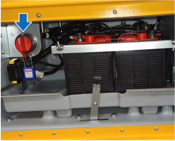
1-A Open the LV battery compartment and ensure that the battery disconnect switch is in the “OFF” position. Lock the red handle with a padlock.
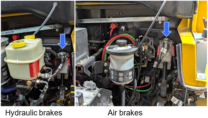
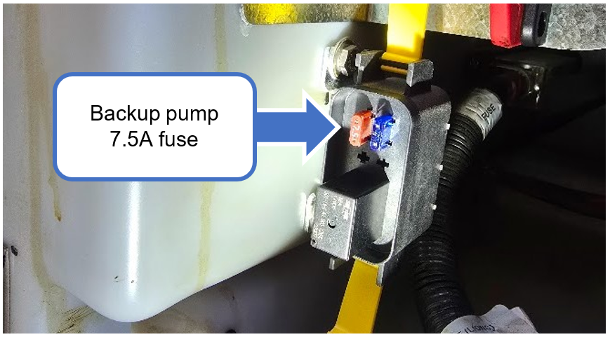
1-B Below the battery disconnect switch, locate the fuse holder box.

1-C Remove the cover and remove the 7.5A fuse from the fuse holder. Other components should remain in place.

By disconnecting this 7.5A fuse, the vehicle’s hydraulic brake booster back-up 12V pump is disabled.
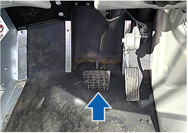
1-D With the ignition switch in the OFF position (no key present), press the brake pedal multiple times. The pedal must remain stiff and difficult to depress. The brake booster backup pump should not start.
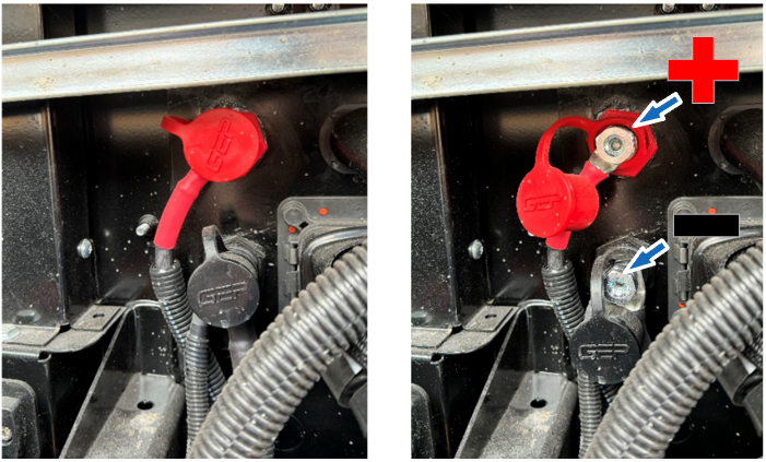
1-E Open the hood. Locate the power and ground passthrough studs on the firewall. Using a multimeter, confirm there is no voltage between the positive and negative studs

#
Preliminary steps - Pneumatic braking system
2-A Open the LV battery compartment and ensure that the battery disconnect switch is in the “OFF” position. Install a padlock on the red handle.

2-B Open the hood. Locate the power and ground passthrough studs on the firewall. Using a multimeter, confirm there is no voltage between the positive and negative studs.
#
Ignition solenoid connections inspection
3-A On the firewall, locate the ignition solenoid above the steering shaft.
3-B Retorque the nuts of the solenoid as presented in the figure below.

3-C Apply Nyogel 760G grease on all the torqued fasteners.
3-D Ensure the ignition solenoid's cables are secured away from the steering shaft; use cable ties.

#
FLEC fusebox connections retorque (if equipped)
4-A Open the hood, and locate the FLEC fusebox.
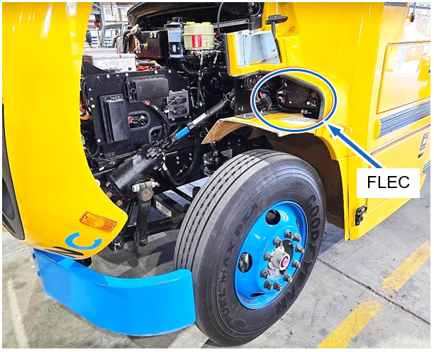
4-B Remove the protective caps from the top three studs.

4-C Torque the nuts to 15 Nm. Use a ¼” drive torque wrench.

#
PDC Eaton fusebox retorque (if equipped)
5-A Under the hood, locate the PDC Eaton fusebox.

5-B Remove the left-hand side cover that protects terminal connections and remove the fusebox cover by rotating the yellow knob.
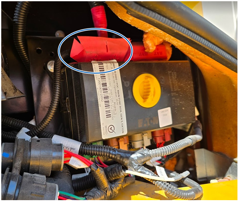
5-C Retorque the two left-hand side nuts on the input studs as shown in the Figure below. Some vehicles have connections on the right side too. Retorque these as well. Use a ¼” drive torque wrench.

#
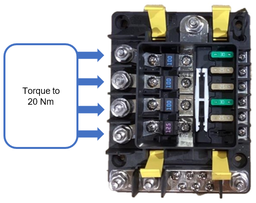
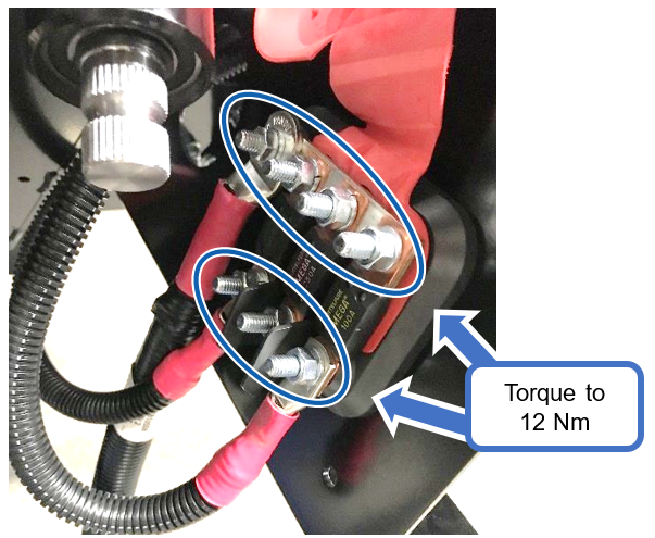
Megafuse fusebox studs retorque (if equipped)
6-A Under the hood, locate the Megafuse fusebox near the steering shaft.

6-B Temporarily detach the top cable to gain access to the yellow clips. Unlock the clips and remove the cover.

6-C Retorque the four (4) left-hand side nuts as illustrated in the figure below:
6-F Reinstall the protective cover and close the yellow clips.
6-G Reconnect the top power cable on its stud and torque the nut to 20 Nm.

#
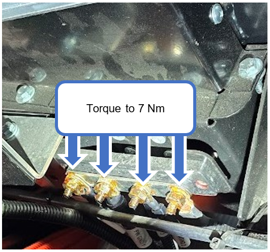
Fuse holder busbar retorque (if equipped)
7-A Under the hood, locate the fuse holder busbar near the steering shaft.
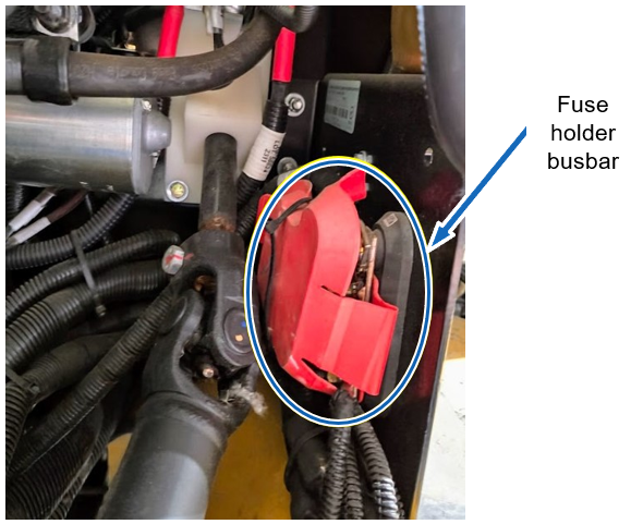
7-B Cut the cable tie and move the red protective cover.
7-C Retorque the seven (7) lug nuts on the input studs, as illustrated in the figure below.
#
Hydraulic brake booster connections retorque
8-A Under the hood, locate the hydraulic brake booster behind the master cylinder.

8-B Torque the backup pump ground cable screw to 7 Nm.

8-C Torque the backup pump power stud nut to 2 Nm.

#
High current relay connections retorque
9-A Under the hood, locate the high current relay on the firewall. It’s positioned on the driver’s side, underneath the power steering fluid reservoir.
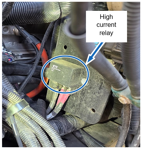
9-B Retorque the two lug nuts on the input studs to 5 Nm.

#
Ground busbar connections retorque
10-A Under the hood, locate the ground busbar positioned above the Settima power steering pump, approximately at the center of the firewall.
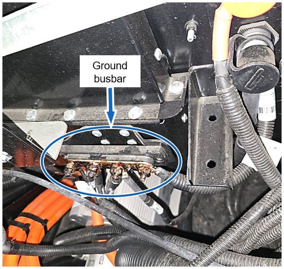
10-B Tighten the stud nuts to 7 Nm.
#
Final validation
11-A Replace the 7.5A fuse back to its original position (hydraulic braking system only).
CAUTION Ensure that the battery disconnect switch is in the “OFF” position.
11-B Hydraulic Braking System: With the start switch in the “OFF” position (no key present), press the brake pedal multiple times. The brake booster pump activation sound must clearly follow each pressing of the pedal.

11-C Turn the battery disconnect switch to “ON” position.
11-D Turn the start switch to “START” position to activate the high-voltage system.
11-E Under the hood, locate the power and ground passthrough studs on the firewall. Using a multimeter, measure the voltage between the positive and negative passthrough studs to validate the presence of a stable 12V voltage.

11-D Ensure there are no DTCs (Diagnostic Trouble Codes) displayed on the multifunction screen.
11-E Perform a drive test to validate the vehicle’s functionality:
• Put the drive selector in “D” (Drive) and move the vehicle forward a few meters.
• Select “N” (Neutral).
• Put the drive selector in “R” (Reverse) and move the vehicle rearward a few meters.
11-F Confirm there is no DTC present on the display at the end of the test.