#
03-22 Steering system inspection and lubrication
#
Front Suspension of Lion Electric Buses - Preventive Maintenance
Following appropriate inspection procedures is important to help ensure the proper maintenance and operation of the front suspension system and components function to their highest efficiency.
#
Inspection intervals
RECOMMENDED INSPECTION INTERVALS PRE-DELIVERY INSPECTION FIRST IN-SERVICE INSPECTION PREVENTIVE MAINTENANCE
Visual inspection for proper assembly and function. Check all the following and replace components as necessary:
• Signs of unusual movement, loose or missing components
• Signs of abrasive or adverse contact with other components
• Damaged, or cracked parts
• Improper suspension function or alignment
Within the first
200 km Within the first
600 Km
or 100 Hours 40,000 km
Every 3 months or whichever comes first
Visually inspect the overall condition, torque and for any signs of damage to:
• Axle assembly
• Leaf spring assembly
• Rear shackle brackets and shackle plates
• Clamp group
Inspect all fasteners for proper torque using a calibrated torque wrench with special attention to the front and rear spring eye and rear shackle connections. 160,000 Km
Every 12 Months or whichever comes first
#
Component Inspection
• Clamp group — Check torque of clamp group mounting hardware.
• Fasteners — Look for any loose or damaged fasteners on the entire suspension. Ensure all fasteners are tightened. Use a calibrated torque wrench to check torque in tightening direction. As soon as the fastener starts to move, record the torque. Correct the torque if necessary. Replace any worn or damaged fasteners.
• Front hangers and shackle brackets — Check for proper fastener torque values using a calibrated torque wrench. Check for cracks or loose mounting hardware. Replace if necessary.
• Operation — All steering components must move freely through the full range of motion from axle stop to axle stop.
• Shock absorber — Look for any signs of dents or leakage; misting is not considered a leak.
• Steel leaf spring — Look for cracks. Replace if cracked or broken.
• Steering pivot points — Check for looseness at all pivot points. Inspect and lubricate all pivot points.
• Front axle — Inspect for any cracks or dents on the axle. Replace as necessary.
• Tire wear — Inspect tires for wear patterns that may indicate suspension damage or misalignment.
• Top pad and bump stop — Check for cracks and/or missing rubber bump stops. Replace if necessary.
• Wear and damage — Inspect all parts of suspension for wear and damage. Look for bent or cracked parts. Replace all worn or damaged parts.
#
Lubrication
Tools and Consumable
- NLGI 2 multipurpose grease
- Grease gun
- Rag
Procedure – Steering Bar
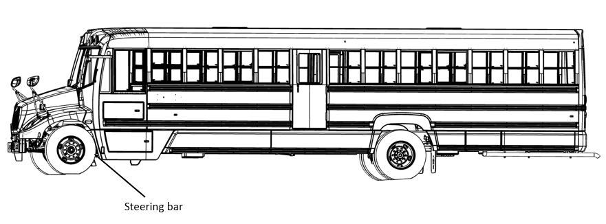
- Make sure the vehicle is on a flat and level surface.
- Make sure the parking brake is on.
Do not lift the vehicle
- Go under the vehicle and visually inspect the front axle for grease leakage.
- Locate all the grease fittings and clean them with a rag (figure 2)
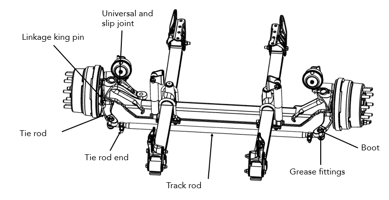
- Apply grease to the tie rod end until the new grease is visible on the other side.
- Apply grease to the drive rod as well as to the universal and sliding joint of the intermediate shafts.
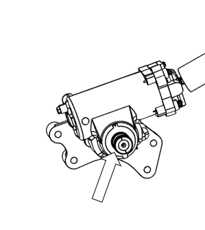
Procedure – Power Steering Box
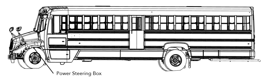
- Make sure the work can be done safely.
- Make sure the two front wheels are straight and parallel during the inspection.
- Turn the ignition key to ON.
- Turn the steering left and right to make sure the that if there is any play in the steering it is maximum 3/8 inch (10 mm).
- Make sure the adjustable steering wheel mechanism works, and the steering wheel stays in place once adjusted.
- Make sure the front wheels turn at the same time and in the same direction as the steering wheel.
- Inspect the system to make sure the steering system is not deteriorated, damaged or worn to the point of affecting the operation of the vehicle.
- Make sure no parts are cracked, broken, missing or misaligned.
- Verify all joints and all sliding joints to make sure there is no play.
- Wipe the grease fittings.
- Using a grease gun, apply grease to the sliding joints (figure 2).
| Front axle - Greasing and Lubrication Specifications | |||
|---|---|---|---|
| COMPONENT | Greasing Intervals | Grease | Outside Temperature |
| KINGPIN BUSHINGS | Maximum of 40,000 km or 90 days, whichever comes first |
Multipurpose Grease NGLI Grade 2 * |
Refer to the lubricant manufacturer's specifications for the temperature service limits applicable to your area. |
| TIE ROD ENDS | |||
| DRAG LINK | |||
* Lubrication greases acceptable for use on the LionC axle will carry a designation of NLGI #2 EP and rated GC-LB or equivalent.
#
KINGPIN LUBRICATION
Upper kingpin grease zerks are located on the inboard side of the steering knuckle and upper kingpin connection. On some models, a grease Zerk is located on the bottom of Iower steering knuckle on the inboard side. On older axles, kingpin grease zerks are located on the top and bottom of the kingpin grease caps.
Procedure
Prior to greasing the kingpins on the vehicle, the suspension must be in a loaded condition.
1. Place vehicle on the ground.
3. Clean off all the grease zerks and grease gun tip with a clean shop towel prior to lubrication.
4. Lubricate the kingpins through the grease zerks.
5. Force the required lubricant into the upper and Iower kingpin grease zerks, until new lubricant flows out from the upper kingpin connection and steering knuckle and the thrust bearing purge location.
Greasing at the Iower zerk should purge grease from the thrust bearing shell. There is two different thrust bearings; composite style thrust bearing and steel roller thrust bearing. Both purge in the same area.
#
TIE-ROD ENDS LUBRICATION
1. Turn the vehicle wheels straight ahead.
2. Wipe the grease zerk and grease gun tip with clean shop towels.
3. Wipe the seal/boot clean with shop towels.
4. Attach a grease gun to the grease zerk. Either a hand or pneumatic grease gun is acceptable. If air operated grease gun is used, system air pressure should not exceed 150 psi.
5. Dirt, water, and discolored old grease should flow from the relief vents or purge holes near the boot crimp area.
6. Continue to purge grease until fresh grease flows from the purge area.
If a tie-rod end does not accept grease, replace the grease zerk. If greasing is still impossible, replace the tie rod end.